Video Wall Daisy Chain vs. Controller: Choose the Signal Architecture
Compare LCD video wall loop-through, tiling, controllers, and multi-output players. Specify sources, layouts, output modes, and recovery before ordering.
A daisy chain describes a connection path. A video wall controller describes a processing role. They are not interchangeable specifications. To choose an LCD video wall architecture, define what each panel must display, which sources can appear at the same time, and what the wall must do when a source or connection fails.
A wall showing one fixed canvas has different requirements from a wall combining several live sources. Establish that distinction before comparing box prices or counting HDMI ports.
Draw the picture before drawing the cables
Describe three intended operating scenes: the normal display, the most demanding required layout, and the fallback state. For each, identify the source, content, destination panels, and whether operators must change the layout during use.
“One image across four panels” and “four independent images” may have the same panel count but require different processing. A single combined canvas also needs a defined relationship between source pixels, panel pixels, and the regions each panel displays.
The LCD video wall buying guide covers the wider project. This article isolates the signal architecture so it can become an explicit part of the quote.

Separate loop-through, tiling, and control
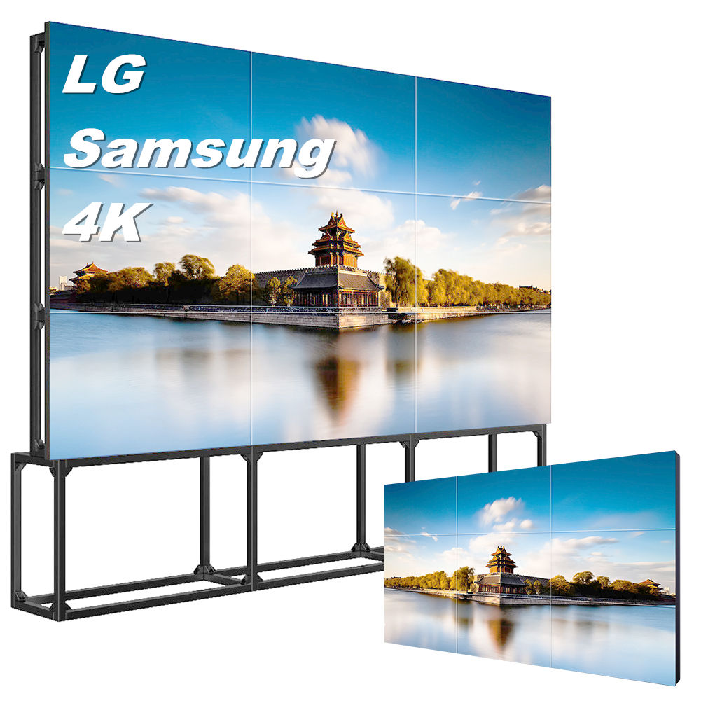
On a display with supported video loop-through, one display can pass a signal to another through its designated output. The panels may then use a tiling function to show their assigned portions of the canvas. The supported ports, signal formats, chain length, and settings belong to the particular display documentation.
ViewSonic's documented daisy-chain example uses DisplayPort connections and separate tiling settings. It illustrates why connecting cables and assigning the image regions are different tasks. It is not a Gemdragon wiring instruction.
A control connection is another separate path. Linking displays for commands does not, by itself, transport the picture. Label video, control, network, and power on the drawing so an installation team can distinguish them.
Scroll horizontally if needed to read all columns.
| Architecture | Useful question | Evidence needed |
|---|---|---|
| Display loop-through with tiling | Can these exact displays distribute and crop the required signal? | Input/output documentation, supported modes, tiling limits, demonstrated layout |
| External controller or processor | Can it create every required layout from the proposed sources? | Input/output matrix, processing limits, control workflow, demonstrated scenes |
| Player with several outputs | Can this player and software address the outputs in the required relationship? | Output capabilities, application support, synchronization evidence where required |
These arrangements can also be combined. An external controller may feed groups of loop-through displays. Evaluate the complete path rather than assigning capabilities based on the architecture's name.
Specify the actual source and output modes
Record input resolution, refresh rate, content format, output mode, rotation, and the destination of each connection. Identify adapters and the installed cable routes. A processor accepting a high-resolution input does not automatically provide that resolution independently to every output.
For example, splitting one source image into four regions is different from delivering four separate full-resolution source images. Keep the source canvas and the physical panel array on the same worksheet. Use the 2x2 and 3x3 planning guide for the related layout decision.

Check source switching as well as steady playback. Decide what the operator should see during a change, whether layouts must be retained after restart, and which configuration tools remain available. Where protected content is required, confirm the documented support of the complete path rather than assuming that a visible connector resolves it.
Test interruptions at the component that can fail
With the equipment supplier's approved procedure, test a source disconnect and recovery, a processor restart where applicable, and the relevant display restart behavior. Record which panels lose the picture and what staff must do to restore the agreed scene.
A serial connection path can create dependencies between upstream and downstream equipment. The exact behavior during standby, signal loss, or power loss must be established for the selected products. Do not claim that every daisy chain has the same failure behavior.
Use motion that crosses a seam if continuous motion matters. A static logo can look correct while concealing a timing issue. The multi-screen synchronization guide explains why a shared playlist and frame synchronization are different requirements.

After choosing the architecture, define the operator preset records and panel identity map needed for handover. For a networked video proposal, review AV-over-IP transport and its separate control path with the IT owner.
Make the quote describe the finished wall
Request a connection drawing, source/output schedule, accepted scenes, equipment identities, control method, cable responsibilities, service access, and recovery instructions. Keep bezel compensation as a separate content decision; see the bezel-compensation guide.
Gemdragon's LCD video wall range is the starting point for the panel requirement. Send the array dimensions, source list, simultaneous layouts, intended motion, installed cable routes, and operator workflow. Request a Quote for a proposed panel-and-processing package, with any configuration limits stated explicitly.