AV over IP for LCD Video Walls: Separate the Video Network From Display Control
"AV over IP" describes where the picture travels. It says nothing about how the panels are controlled, where content updates arrive, or who signs for the switch configuration. Draw them as three logical paths, even if some share the same physical infrastructure.
This is written for the two people who end up owning that split: the IT owner asked to approve the switch work, and the AV integrator who has to make the picture appear. Split the drawing before you size anything.
Three paths that must be drawn separately
Here is the split in prose, because a real drawing needs your topology rather than ours.
Live video transport. Sources feed encoders or a networked video source. Their packets cross switches to decoders, which turn them back into pictures. Those pictures reach the wall either at each panel or through a video wall processor that accepts standard video inputs. Whether a specific processor takes networked video itself, or sits behind external decoders, is a property of that processor.
Management and control. A control device, a processor's management interface and the panels themselves exchange commands, status and configuration. That function may use Ethernet, serial, or both. Its documented control capability does not establish a video-decoding capability. The distinction matters at changeover, when somebody assumes a network socket on the back of a display must be a video input.
Cloud and content updates. If a separate media player generates the content, its downloads, schedules and API calls form a third path with its own requirements. The digital signage network requirements guide covers that as a player-and-services problem, including offline behavior.
Scroll horizontally to see all columns.
| Path | What crosses it | Often mistaken for | Who owns it | Evidence to obtain |
|---|---|---|---|---|
| Live video transport | Encoded picture packets: source encoder to decoder | A control port or a management interface | AV integrator, with IT for switching | Documented topology, stream counts, multicast behavior, firmware baseline |
| Management and control | Commands and status: control device to processor and panels | Picture transport or an audio return | AV integrator, with IT for addressing | Documented control method, what state it reports, who may use it |
| Cloud and content updates | Downloads and API calls: player to content services | Live video or remote-control traffic | Content owner with IT and security | The chosen platform's current requirements, tested on the site network |

Two boundaries belong in writing, because both get assumed.
A control connection is not a native video decoder. What a device is designed to do is answered by its documentation, not by the shape of its socket. Plenty of equipment accepts commands over Ethernet while receiving pictures over HDMI.
A decoder is not automatically the wall. A video wall processor may accept HDMI from an external decoder, and one decoder may serve processing that drives several panels. Endpoint counts and topology depend on the actual processor and decoder design. Decoders can also sit at the wall, in the rack, or in a cabinet between the two, and that choice changes power, cooling, cable runs and who can reach them. Put it on the drawing.

Count streams per link, not sources times viewers
Bandwidth arguments usually start with a large, reassuring multiplication. On a switched network that is the wrong arithmetic, the way counting letters instead of envelopes is the wrong arithmetic for a mailbox.
What matters at any single link is the number of distinct streams crossing it, at the bitrate the vendor documents for the deployed mode. In a multicast design, one encoded stream can be received by many decoders on the same switched fabric, and the switch replicates it where paths diverge. One source shown on nine panels is one stream upstream of the split point. Some designs use point-to-point flows instead, and then the count changes. The vendor's documented behavior for the exact product decides which arithmetic applies.
A deliberately fictional example shows the method. Suppose the selected encoder documents 600 Mbps for the chosen setting, four distinct sources must reach the wall, and the switch replicates at the wall side. That uplink carries four streams: 4 × 600 Mbps = 2.4 Gbps, before accounting for the selected system's overhead, other traffic, or design margin. The numbers describe a project that does not exist. The question they illustrate is which streams cross this link, not how many screens exist.
Scroll horizontally to see all columns.
| Link in the topology | Distinct streams crossing | Documented bitrate per stream | Planning allowance | Total to carry | Who confirmed it |
|---|---|---|---|---|---|
| Source-side access switch | |||||
| Distribution or uplink | |||||
| Wall-side switch | |||||
| Any link shared with other site traffic |

The IT review that prevents a redesign
Do this before the purchase order, not after the first demonstration.
- Multicast behavior as documented. Ask for the vendor's stated switching requirements, including any snooping and querier function the design needs and what happens when the network lacks it. Crestron's AV-over-IP network design documentation states that its DM NVX platform uses multicast and requires specific switching, IGMP snooping and a querier, plus deliberate topology planning. That describes DM NVX, and shows why documented vendor requirements, rather than a general belief about "AV networks", belong in front of IT.
- Uplinks and oversubscription. Confirm where streams converge and what the design does with several high-bitrate flows on one uplink.
- Firmware and interoperability. Record what will be installed and who keeps encoder, decoder and switch software inside the vendor's supported combinations.
- Access and monitoring. Decide who may change encoders, decoders and switches, and how the operations team learns that a stream has stopped rather than a panel being off. Extron's AVoIP design guide page points to network management and IGMP; the selected platform's current documentation is still needed for its actual network requirements.
- Timing, fallback, and recovery. Keep the end-to-end latency requirement distinct from network reachability. Agree what the wall does when a stream is lost or the network is under maintenance, and who executes the fallback.
This article supplies no firewall openings, switch commands or VLAN designs; those come from your own network standards and the selected vendor's documentation. Nor does anything here permit disabling a security control to make a demonstration work. A wall that only performs with a protection switched off has not been commissioned.
FAQs
Does a video wall need its own separate network?
Sometimes, and that decision belongs to the site's network owner rather than the wall supplier. What matters is that transport and control each have a documented design with an owner, and that the chosen equipment's requirements were reviewed against it.
Can video over IP share the office network?
Only after the documented stream load has been compared with existing traffic, and after someone has decided what happens during a maintenance window or a congested afternoon. The accounting above is how that comparison starts.
Is one decoder needed per panel?
That depends on the processor and decoder design: one decoder may feed processing that drives several panels, or each panel may terminate its own feed. Ask for documented endpoint counts for the exact products.
Next step
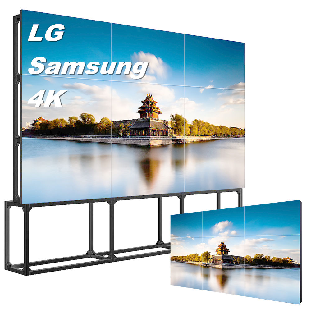
Gemdragon's LCD video wall range is the panel side of that drawing. Wall configurations are organized around one of several signal arrangements (a signal distributor, a video wall processor, a matrix switcher or a daisy chain), chosen for the project rather than installed as a set, with any limits stated in the proposal. How the picture arrives, and whether a processor or external decoders deliver it, is a configuration decision we can work through with your integrator and your network owner.
Send the proposed topology, source count, and processor or decoder under consideration. Identify the hardware documentation and network review needed for that configuration.
Browse the LCD video wall range or start a configuration conversation with the drawing.
Related reading: daisy chain versus controller covers the signal-architecture choice next to this one; the LCD video wall buying guide covers the wider project.