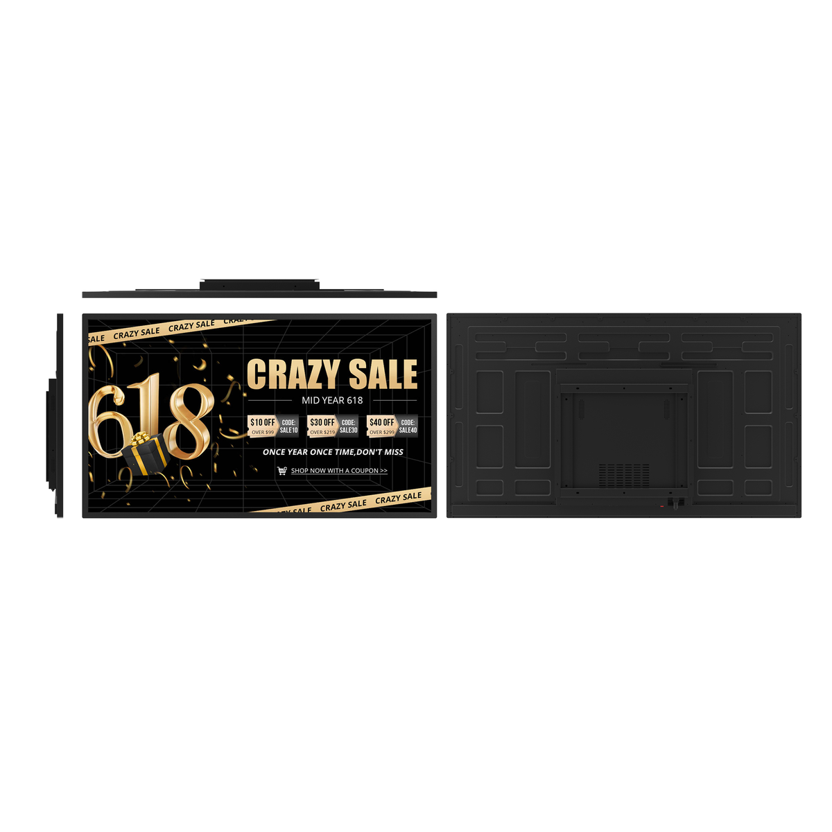
Wall-Mounted Digital Signage in Corridors: Measure the Finished Projection
A finished-assembly projection worksheet for facilities and AV teams planning wall displays along circulation paths.
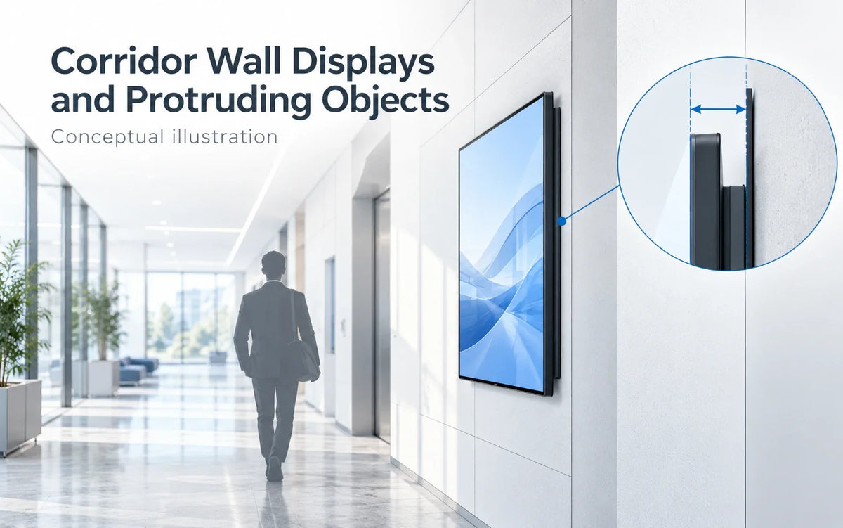
Cover illustration: review projection from the finished wall to the front of the display assembly.
A wall-mounted display can look slim in a product photograph and still project too far into a corridor once its bracket, tilt, cable space, and surrounding frame are installed. For a circulation-path review, measure the finished assembly from the relevant wall surface to its furthest projecting part. Cabinet thickness is only one input.
For a U.S. project, give that installed section to the person responsible for accessibility review before the wall work is fixed. A screen size, a low-profile bracket label, or an attractive elevation does not answer the projection question.
Start with the scope of the protruding-object rule
The U.S. Access Board's ADA Standards, section 307.2 limit horizontal projection into a circulation path to 4 inches (100 mm) for objects whose leading edges are more than 27 inches (685 mm) and not more than 80 inches (2030 mm) above the finished floor or ground. Section 307.5 also protects required clear width. These are distinct checks.
The Board's protruding-objects guide explains that the concern extends beyond designated accessible routes to circulation paths more generally. It illustrates approaches such as recessing objects and using appropriately designed detectable elements. Their suitability depends on the complete arrangement, including other required clearances.
This is a planning guide for the display assembly, rather than a determination that a particular building or product complies. Ask the project's qualified reviewer to apply the relevant requirements to the actual location. A different mounting height is not a shortcut around the rest of the accessibility and viewing assessment.

Draw the installed section, including the unglamorous parts
An elevation shows the screen's face. A section through the wall and equipment shows what occupies the corridor. Request both, using the selected display, mounting hardware, and finish details.
Mark the finished wall plane, rear mounting interface, bracket position, display enclosure, front trim, and any control or accessory that extends farther. Include the intended operating angle. A tilted display may have a different leading point from the same display held parallel to the wall.
Be careful with dimension definitions. A bracket specification may measure from the wall to the display's mounting interface, or may describe a complete installed depth. Adding a cabinet dimension to a figure that already includes it counts the same space twice. Conversely, using only the bracket's depth leaves out the display. Put the endpoints of each dimension on the drawing before calculating anything.
Cable plugs and bend space need a separate check. A connector may prevent the display from reaching the position shown in a tidy rendering. Do not flatten the cable, force the plug, or improvise a wall recess to recover a dimension. Resolve the arrangement with the equipment and site teams.
A projection review sheet
Use this worksheet to assemble the evidence. It is a proposed project record, not an inspection result.
Scroll horizontally if needed to compare all columns.
| Item | What to establish | What belongs in the record |
|---|---|---|
| Reference surface | Which finished surface bounds the circulation path? | Marked plan and installed section |
| Display | Exact enclosure and selected touch assembly, if any | Matching drawing and revision |
| Mount | Installed position and supported operating angle | Mount identity and dimension endpoints |
| Connections | Actual plugs, adapters, routing, and clearance | Connection detail for the selected configuration |
| Trim or enclosure | Furthest leading edge in normal use | Complete assembly dimension |
| Surrounding space | Required circulation width and nearby obstructions | Site review by the responsible professional |
The result should be one understandable installed dimension with traceable inputs. A folder containing six separate catalog sheets is not yet that result.
Review normal use and servicing separately
An articulating mount may sit close to the wall when closed and extend into the path during maintenance. Record both states. The normal-use review addresses how the public encounters the installed screen; the service plan addresses how authorized staff work around an opened assembly.
Ask who can release the mount, how the area is controlled during service, and whether the display returns to a defined operating position afterward. A service position should not become an undocumented everyday viewing adjustment. Follow the mounting system's intended locking and retention arrangements.
The wall-mounted commercial display buying guide covers bracket, viewing, and service choices more broadly. This review adds the finished projection and the surrounding circulation space to that decision.

If the assembly does not fit, change the design deliberately
First identify what causes the projection. A different supported bracket may help when the stand-off is the problem. It will not necessarily resolve a connector that needs additional space or a frame that projects beyond the screen.
Relocation can be preferable where another wall provides a clear view without the same circulation constraint. A recess is another design option, provided the building construction, equipment clearances, heat path, and removal method support it. The recessed-versus-surface-mounted guide examines those tradeoffs.
Where a protective or detectable architectural element is proposed, have the responsible designer review it as a complete arrangement. Do not place a loose planter under the screen and label the problem solved. The element itself, its permanence, and its effect on clear floor space and routes all matter.
For an interactive installation, add a separate review of approach space, reachable controls, and the application task. Passing one projection check does not establish that a touchscreen can be used independently by its intended audience.

Questions to settle before ordering
Does an ultra-thin display automatically satisfy the projection limit?
No. The installed assembly includes the mount, display, connections, and any frame or accessories. Measure the complete configuration against the actual site conditions.
Can I use the screen diagonal to estimate installed depth?
No. The diagonal describes the screen size. Obtain the enclosure and mounting dimensions for the ordered configuration, then show their relationship in section.
Is moving the screen above the usual viewing position a simple fix?
It changes the design problem. Have the project reviewer assess the new arrangement, including headroom, viewing, circulation, and any interactive requirements, rather than approving it from a single height dimension.
Bring the wall section into the quotation
Gemdragon's Ultra-Thin Wall-Mounted Digital Signage is a single-screen product with optional touch. Select the size and touch configuration before matching the mechanical drawing; the product name alone does not establish the assembly's installed projection.
Request a Quote with the wall location, preferred size, intended use, and a section or photograph if available. Ask for the configuration-specific information your installer and accessibility reviewer need. Open site questions can stay visible in the brief while those parties resolve the installation.
Product photos, catalog renders, and video stills are supplied Gemdragon materials with source-specific captions. Covers and diagrams are conceptual illustrations, not field measurements or installation approvals.